
When one is selected they allow current to flow into the IC from the 5V rail, with the LED in between – turning it on. Pins OUT0~OUT15 are the current-sink pins for each LED. The pinout diagram is quite self-explanatory: Using the IC is very easy on the hardware front. Here is an example, compare the brightness of the LED bars against the display of the CRO – as the brightness increases, the voltage (amplitude ) spreads across the entire time period (horizontal axis) as the brightness decreases, the voltage spread across time retreats: If you alter the period of time between on and off, you can alter the perceived brightness of the LED. But if you switch it on and off very quickly, it does not look as bright (as it is not on 100% of the time). What is pulse-width modulation? Normally an LED might be on, or off. However, it can control the brightness of the LEDs using pulse-width modulation over 4096 steps via software, or using a single resistor. Furthermore, another benefit of this IC is that you don’t need matching current-limiting resistors for your LEDs, as this IC is a current sink, in that the current flows from the 5V rail, through the LED, then into the IC.
#Tlc5940 arduino library download serial#
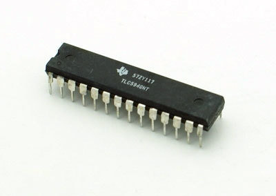
What can this IC do for us? It can control 16 LEDs per IC, and also be cascaded to control more and more, with the display data arriving via a serial line in the same manner as a 74HC595 shift register. Also available in HTSSOP and QFN packaging. Moving along, here is the IC:Īnother nice big DIP IC.

If you have a common-cathode display module, you should have a look at the Maxim MAX7219. My reason for doing this is to demonstrate another, easier way of driving many LEDs as well as LED display modules that are common-anode.
#Tlc5940 arduino library download driver#
Today we are going to examine the Texas Instruments TLC5940 16-channel LED driver IC.


 0 kommentar(er)
